

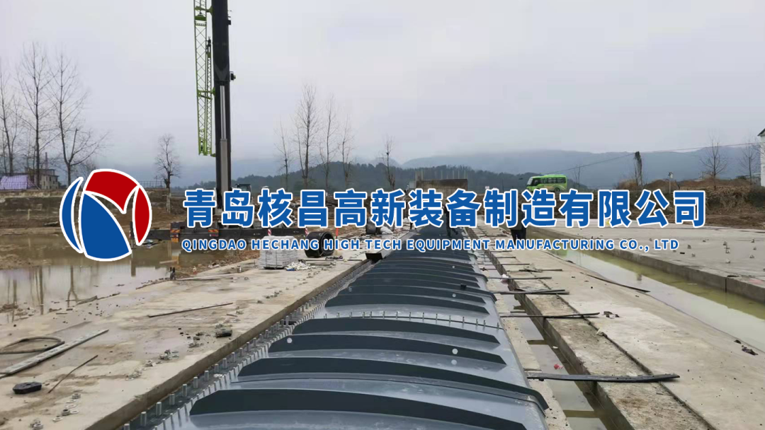
I. Technical Specifications for Installation of Airbags and Shield Plates Standards for Equipment Incoming Inspection Airbag appearance inspection: No scratches or bubbles on the surface; adhesive layer bonding strength ≥ 2.5N/mm; Shield plate inspection: Radian deviation ≤ ±3mm; plate surface flatness ≤ 2mm/2m; anti-corrosion coating thickness ≥ 80μm. Analysis of Core Installation Process Setting-out and positioning: Mark the airbag installation contour line on the foundation surface according to the drawings, with an error ≤ ±5mm; Airbag positioning: Use a dedicated lifting belt to hoist in three sections to avoid excessive stretching; after positioning, check whether the bottom sealing rubber strip is compacted; Inflation pressure test: Pressurize in three stages (0.08MPa → 0.10MPa → 0.12MPa). During pressure stabilization at each stage, inspect: ① Airbag deformation ≤ 5%; ② Shield plate displacement ≤ 3mm; ③ Air leakage at each joint < 0.5L/min; Limit belt installation: The connecting bolts between the limit belt and the shield plate must be tightened diagonally, with a pre-tightening force of 30-35N・m to ensure accurate positioning during dam lifting and lowering. II. Key Points for Integration and Commissioning of Electromechanical Systems Technical Parameters for Equipment Installation Fan installation: Levelness deviation ≤ 0.1mm/m; uniform compression of shock-absorbing pads; flexible connections for inlet and outlet pipes; Pipeline system: Pneumatic pipes use Φ89×4mm galvanized steel pipes; after welding, conduct a 0.15MPa air pressure test (1.25 times the working pressure), with pressure drop ≤ 0.005MPa within 30 minutes of pressure holding; Control system: PLC control cabinet must be grounded (grounding resistance ≤ 4Ω); dam height sensor accuracy reaches ±10mm, response time ≤ 2 seconds; airbag overpressure protection value is set to 0.15MPa, low-pressure alarm value to 0.07MPa. Linkage Commissioning Process No-load test run: Fan operates continuously for 8 hours, with bearing temperature rise ≤ 40℃; Load commissioning: Simulate flood dispatch to achieve dam height lifting from 2m to 5m within ≤ 6 minutes. After 5 repeated operations, inspect: ① Airbag pressure fluctuation within 0.08-0.12MPa ≤ ±0.002MPa; ② Control system error ≤ ±0.5%; ③ No abnormal wear on moving parts. III. Construction of Emergency System for Flood Control and Flood Season Management Organization and Monitoring Mechanism Establish a three-level flood control team: ① Command team (project manager): Overall coordination of emergency rescue and dispatch; ② Monitoring team (2 personnel): Observe water level 6 times a day (accuracy ±50mm) and record meteorological data; ③ Emergency rescue team (15 personnel): Equipped with 1 excavator and 1 loader, on standby at all times. Material Reserve and Emergency Plan Flood control material list:
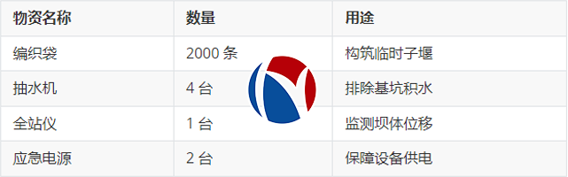
Measures for high water level: When the water level exceeds the designed flood level by 0.5m, immediately start the standby blower to replenish air to 0.12MPa, and organize personnel to evacuate 50m away from the embankment line. IV. Technical measures for flood control during the construction period Foundation construction stage: Set up steel sheet pile cofferdams (height 2m) at the upstream and downstream, excavate drainage ditches (300mm in width × 400mm in depth) on the inner side, and equip 2 Φ150mm water pumps for drainage; Equipment installation stage: Measure the dam displacement twice a day at 10:00 and 22:00. If the displacement exceeds 10mm, the anchoring system must be inspected; Rainy season construction: Check the 72-hour weather forecast before concrete pouring. Pouring is prohibited in moderate rain or heavier weather, and the poured parts shall be covered with plastic sheets for maintenance.